
Beam Extra Bar Length Exact Formulas for Top and Bottom Bars
Learn the exact beam extra bar length formulas for top and bottom reinforcement in RCC beams. Simple step-by-step calculations using SP 34 rules, two real worked examples, comparison tables, and common site mistakes to avoid.
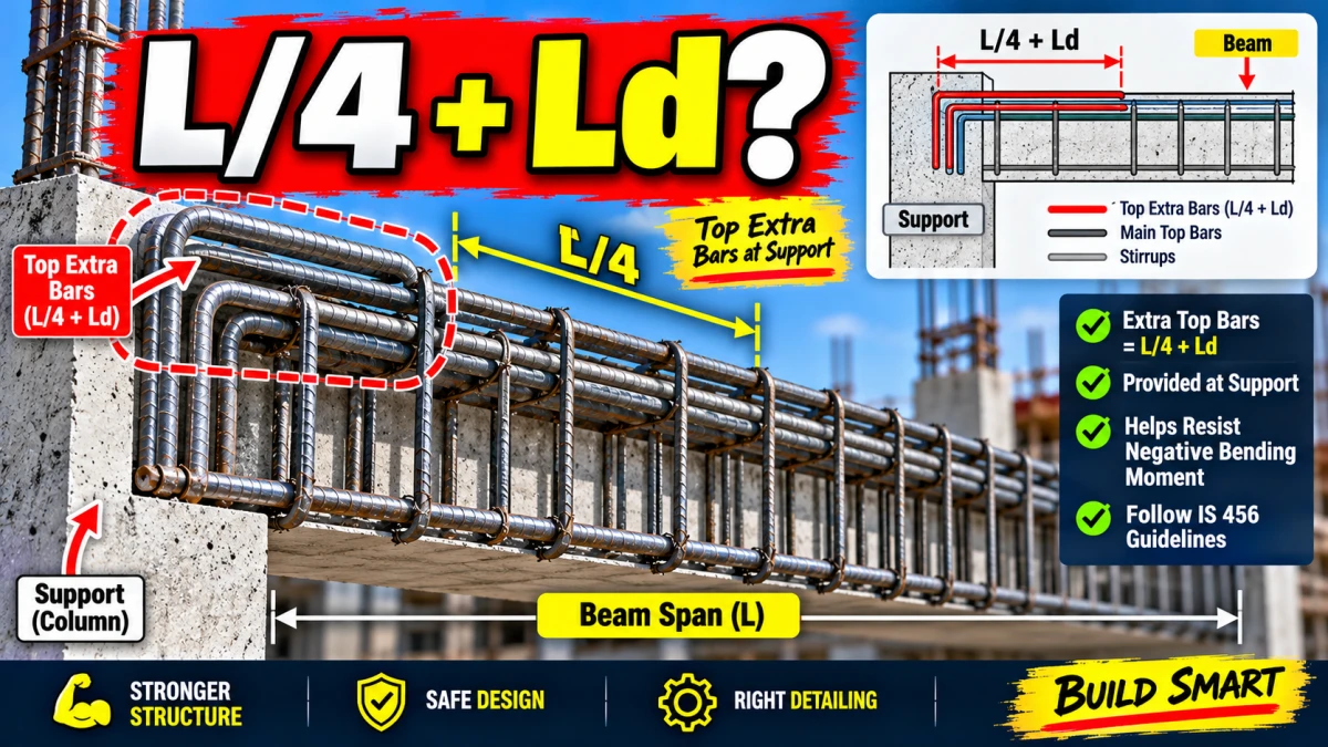
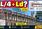
Beam extra bar length is the additional reinforcement length provided beyond the main bars at critical zones of an RCC beam. Top extra bars cover negative moments near supports. Bottom extra bars cover positive moments at mid-span. As per SP 34 guidelines, top extra bars at end supports equal L/4 plus development length, while bottom extra bars equal roughly 0.75L for continuous spans after leaving 0.1L and 0.15L clearances from supports.
Extra bars prevent cracks and failure where bending moments peak. Main continuous bars alone often fall short in these high stress zones. Site engineers and beginners must calculate these lengths correctly for accurate bar bending schedules and safe construction.
Why Extra Bars Are Needed in Beams
Bending moment changes along a beam. Positive (sagging) moment peaks at mid-span and puts the bottom face in tension. Negative (hogging) moment peaks at supports and puts the top face in tension.
Main bars handle average forces. Extra bars add capacity exactly where forces are highest. Without them, cracks appear first at mid-span bottom or near supports on top. SP 34 and IS 456:2000 require proper curtailment and extension of reinforcement to match the moment diagram.
In simply supported beams the bottom needs extra bars near the centre. In continuous beams both top and bottom extras become important.
Difference Between Top Extra Bars and Bottom Extra Bars
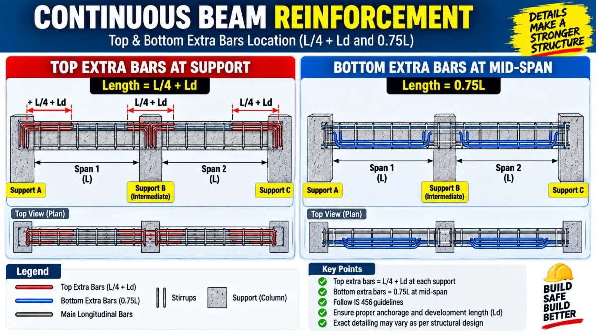
Top extra bars resist negative moments. They sit near supports and extend into the span. Bottom extra bars resist positive moments. They sit in the central portion of the span.
| Feature | Top Extra Bars | Bottom Extra Bars |
|---|---|---|
| Moment type | Negative (hogging) | Positive (sagging) |
| Location | Near supports | Mid-span |
| Typical length rule | L/4 + Ld (end supports) | L – 0.1L – 0.15L ≈ 0.75L |
| Continuous beam note | Longer at intermediate supports | Leaves clearances from both supports |
| Simply supported note | Often limited or none | Full mid-span coverage needed |
This table shows the core difference beginners must remember on site.
Standard Formulas for Beam Extra Bar Length (SP 34)
SP 34 Handbook on Concrete Reinforcement and Detailing gives practical simplified rules for beams under uniformly distributed loads with roughly equal spans.
Top Extra Bar Length
- At end support: (Effective span L / 4) + Development length (Ld)
- At intermediate support: (L1 / 4) + (L2 / 4) + support thickness
Ld is calculated from IS 456. For Fe 500 bars in M20 concrete it is commonly taken as 40d to 50d (d = bar diameter). Always check the design drawing first.
Bottom Extra Bar Length
For a continuous span L:
Bottom extra length = L – 0.1L – 0.15L = 0.75L
- Leave 0.1 times effective span from the centre of the end support.
- Leave 0.15 times effective span from the centre of the intermediate support.
These distances keep the extra bars only in the high positive-moment zone.
Development Length Reminder
Ld = (φ × σs) / (4 × τbd)
Where φ is bar diameter, σs is design stress, and τbd is design bond stress. Site practice often uses 40d for Fe 415 and 50d for Fe 500 in normal conditions.
Worked Example 1 Simply Supported Beam
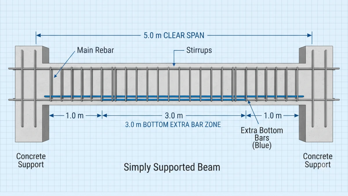
Consider a simply supported beam with clear span 5.0 m. Columns are 300 mm wide. Effective span L ≈ 5.3 m (centre-to-centre). Use 16 mm Fe 500 bars. Assume Ld = 50d = 800 mm.
Bottom extra bars are required at mid-span.
Practical length often taken as L/3 to L/2 of clear span, or follow the design drawing.
Using a conservative site approach: bottom extra length ≈ 0.6 × 5.0 m = 3.0 m.
Top extra bars are minimal in a pure simply supported case unless partial fixity exists. If provided near ends they follow L/4 + Ld ≈ 5.3/4 + 0.8 = 2.125 m total length each side.
Cutting length of each bottom extra bar = 3.0 m + any required hooks or bends (add 9d or 12d per hook as per drawing).
This example shows how a single span focuses extra steel at the centre bottom.
Worked Example 2 Two-Span Continuous Beam
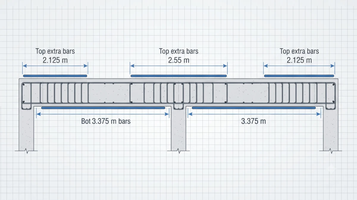
Take a continuous beam with two equal effective spans L1 = L2 = 4.5 m. Intermediate support thickness X = 300 mm. Use 20 mm Fe 500 bars. Ld = 50d = 1000 mm.
Top extra bars
- Left end support: (4.5 / 4) + 1.0 = 1.125 + 1.0 = 2.125 m
- Right end support: same = 2.125 m
- Intermediate support: (4.5 / 4) + (4.5 / 4) + 0.3 = 1.125 + 1.125 + 0.3 = 2.55 m
Bottom extra bars for each span
= 4.5 – (0.1 × 4.5) – (0.15 × 4.5) = 4.5 – 0.45 – 0.675 = 3.375 m
These lengths match SP 34 recommendations for continuous beams. Always verify against the structural drawing because actual moment coefficients may change the cut-off points.
Comparison of Extra Bar Lengths Across Beam Types
| Beam Type | Top Extra at End Support | Top Extra at Intermediate | Bottom Extra Length |
|---|---|---|---|
| Simply supported | L/4 + Ld (if needed) | Not applicable | ≈ 0.5L to 0.6L |
| Continuous (equal spans) | L/4 + Ld | L1/4 + L2/4 + X | 0.75L |
| Continuous (unequal) | Longer span / 4 + Ld | Based on longer span | Adjusted clearances |
| Cantilever | Full length + Ld into support | Not applicable | Minimal or none |
Use this table on site when drawings are unclear. The numbers come directly from SP 34 simplified rules.
Step-by-Step Calculation Process for Site Use
- Note effective span (centre-to-centre of supports) and clear span from the drawing.
- Identify bar diameter and grade to find Ld.
- Decide if the beam is simply supported or continuous.
- Apply the matching formula for top and bottom.
- Add bend or hook lengths if the bar terminates with a standard bend (usually 9d or 12d).
- Prepare the bar bending schedule entry with exact cutting length.
- Mark the start and end points on the cage with paint or chalk before placing.
Follow these steps every time. Skipping the effective-span check is the most common error.
Common Mistakes That Lead to Wrong Extra Bar Length
Many site teams use a flat L/3 or L/4 for every bar without checking support type. This either wastes steel or leaves the high-moment zone under-reinforced.
Another frequent error is measuring from the face of the column instead of the centre. Effective span must be centre-to-centre.
Forgetting to add development length at the ends of top extra bars is also common. The bar must develop its full stress beyond the point of inflection.
Always cross-check the structural drawing. SP 34 simplified rules apply only when loads are predominantly uniform and spans are nearly equal. For unusual loading, the designer’s cut-off points govern.
Practical Tips for Accurate Placement
Place bottom extra bars only in the central zone after leaving the required clearances. Do not run them full length unless the design demands it.
Keep top extra bars continuous across intermediate supports for the calculated length. This ensures the negative-moment region is fully covered.
Maintain proper clear cover and spacing so concrete can flow around the extra bars. Use chairs or spacers to hold them at the correct height.
In seismic zones follow the additional ductile detailing rules of IS 13920 along with SP 34.
How Extra Bar Length Affects Bar Bending Schedule
Every extra bar appears as a separate mark in the BBS. Incorrect length multiplies across the whole floor and creates either shortage or wastage.
When the calculated length is close to a standard stock length, adjust slightly within code limits to reduce cutting waste. Always record the final cutting length clearly.
Conclusion
Correct beam extra bar length keeps the reinforcement exactly where the bending moments demand it. Use the SP 34 formulas L/4 + Ld for top extras at ends and 0.75L for bottom extras in continuous spans and verify with the structural drawing. The two worked examples above show the method for both simply supported and continuous beams. Apply the comparison table and the step-by-step process on every site. Accurate extra bar lengths save steel, prevent cracks, and produce safer beams.
Frequently Asked Questions

Prince Badaik is the founder of CivilCost, a platform dedicated to making civil engineering calculations simple and accurate for students, engineers, contractors, and homeowners across India.



Comments (0)